


Here is some of my gear artwork.
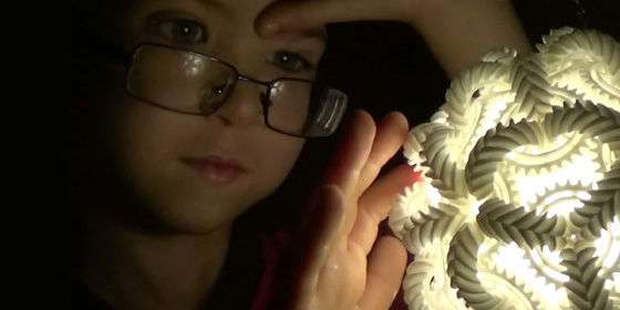
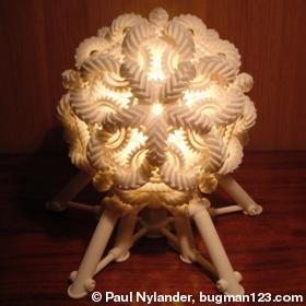
Bucky Brain Gear Kinetic Sculpture / Lamp - POV-Ray 3.6.1 version: 2/7/11, 3ds Max, MaxScript model: 10/5/11
I began working on a project to create a real-life 3D printed model of this system on 10/5/11, but it wasn't until recently that I presented my first complete model at the 3D Printer World Expo 2014. You can read reviews about this work in 3D Printer World, 3D Printing Industry, 3Ders.org, and The Creators Project. On 4/8/14, I successfully motorized all 92 gears. I will post videos when I am ready to begin selling, hopefully soon. Links Triple Gear - three linked gears that are motorized, 3D printed by Henry Segerman 11 Gear Mobius Strip - 3D printed by Josh Mings Hypotrochoid Gear System - by Jvohome, see also this 3D printed model by Stijn van der Linden Other Kinetic Sculpture Links Cyber Dreams, Urban Species - amazing kinetic sculptors by U-ram Choe Octo, In Cloud Light - wind powered kinetic sculptors by Anthony Howe |
242 Gear Sphere - Mathematica 4.2, POV-Ray 3.6.1, 9/26/11
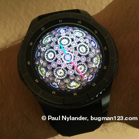 Here is a set of 242 interlocking bevel gears arranged to rotate freely along the surface of a sphere. This sphere is composed of 12 blue gears with 25 teeth each, 30 yellow gears with 30 teeth each, 60 orange gears with 14 teeth each, and 140 small red gears with 12 teeth each. I also found 3 other gear tooth ratios that will work, but this one was my favorite because the small gears emphasize the shape of a truncated rhombic triacontahedron. Click here to download this design as an animated face for your smart watch.
 |
Involute Gears - new version: Mathematica 4.2, 5/23/12; old version: POV-Ray 3.6.1, 7/12/06
 The ideal profile for a gear tooth is the involute of a circle. The exact shape of the involute curve can be defined by the number of teeth, pitch circle radius, and pressure angle. This animation shows a gear with only 6 teeth, which may not be enough teeth for most applications, but it demonstrates a good example of extreme undercut. Here is some Mathematica code to draw ideal gears:
(* runtime: 0.3 second *) n = 9; r = 1.0; a = Pi/9; dtheta = Pi/n; dr = 2r/n; rbase = r Cos[a]; IR = r - dr; OR = r + dr; Rz[x_] := {{Cos[x], -Sin[x]}, {Sin[x], Cos[x]}}; Involute[t_] := rbase((Tan[a] - t){-Cos[a - t], Sin[a - t]} + {Sin[a - t], Cos[a - t]}); Undercut[t_] := r {Sin[t] - t Cos[t], Cos[t] + t Sin[t]} - dr Rz[-t].{Tan[a], 1}; t2i = Tan[a]; t1i = t2i - Sqrt[(OR/rbase)^2 - 1]; t2u = -2 t2i/n; t1u = t2u - Sqrt[rbase^2 - IR^2]/r; Clear[ti, tu]; {t2i, t1u} = {ti, tu} /. FindRoot[Involute[ti] == Undercut[tu], {ti, 0.5 t2i, t2i}, {tu, 0.8 t1u, t1u}]; plist = Join[Table[Involute[t], {t, t1i, t2i, (t2i - t1i)/8}], Table[Undercut[t], {t, t1u, t2u, (t2u - t1u)/8}]]; plist = Join[Reverse[plist], Map[(Rz[-dtheta].{-#[[1]], #[[2]]}) &, plist]]; plist = Join @@ Table[Map[(Rz[-2dtheta i].#) &, plist], {i, 1, n}]; Table[Show[Graphics[Map[(sign = #; Line[Map[{sign r, 0} + Rz[sign theta].# &, plist]]) &, {-1, 1}],AspectRatio -> Automatic, PlotRange -> OR{{-2, 2}, {-1, 1}}]], {theta, 0, 2dtheta(1 - 1/10), 2dtheta/10}]; Links Gear Template Generator - Java applet, by Matthias Wandel Lobe Compressor - SPH simulation by Simerics Paradoxical Gear Set - gears rotating in same direction with 1, 2 and 3 teeth, by Jacques Maurel Mechanical Involute Gears - Mathematica demonstration by Stephan Heiss, here is the source code |
Plywood Gears - VCarve Pro, Laguna CNC router, 3/30/17
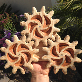
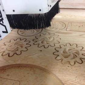 I cut these gears out of 3/4 inch plywood on the CNC router at Urban Workshop. Then I used a handheld router to smooth the edges from splinters, and then nailed them to a board to make this fun toy for the kids. It is a bit crude, but cheap and easy to make using the CNC router.
 |
92 Gear Spheres - Mathematica 4.2, POV-Ray 3.6.1, 9/22/11 (old version: 2/7/11)
 These images show different ways of arranging 92 bevel gears to rotate freely along the surface of a sphere. Each sphere contains 12 large blue gears, 20 large yellow gears, and 60 small red gears. The gears are slightly off-centered from the vertices of a geodesic sphere. When I first attempted this on 2/7/11, I used a 25:30:12 gear tooth ratio, but unfortunately, I couldn't get the teeth to mesh together. However, on 7/26/11, Taff Goch demonstrated that it is possible to get the teeth to mesh reasonably well using a 20:24:13 gear tooth ratio. As it turns out, there are other gear tooth ratios that can be made to mesh together reasonably well, as you can see here. I found these solutions by writing a program that analyzed many different ratios. For a given ratio, the location and radius of each gear was calculated so that there are no gaps between mating pitch circles. Then the gear phase angles were calculated and solutions with large phase errors were rejected. Finally, I did a visual inspection of the remaining solutions and presented some of my favorite ones here. Two more of my favorites are 15:15:8 and 30:30:16 because they only require two gear sizes. It is interesting to note that the number of blue gear teeth must always be divisible by 5 and the number of yellow gear teeth must always be divisible by 3, but the number of red gear teeth does not have to be divisible by anything (it can be a prime number).
Links 92 Gears, 92 Gears Caged - Taff Goch succeeded in getting the gear teeth to mesh, see also his 62 gears sphere |
Bucky Brain Gear - POV-Ray 3.6.1, 1/27/11
 Here is a set of 60 interlocking double bevel gears arranged to rotate freely around the edges of a truncated icosahedron (Buckminsterfullerene), with the gear planes forming the edges of a rhombic triacontahedron. The traditional brain gear is composed of only 8 double bevel gears arranged to rotate freely around the edges of an octahedron, with the gear planes forming the edges of a cube and is a popular subject for stereolithography demonstrations.
Links Motorized Lego brain gear - YouTube video, here is another variation |
32 Gear Sphere - Mathematica 4.2, POV-Ray 3.6.1, 2/7/11
 Here is a set of 32 identical bevel gears arranged to rotate freely on the faces of a truncated icosahedron (Buckminsterfullerene). As a general rule, the number of blue gear teeth must always be divisible by 5 and the number of yellow gear teeth must always be divisible by 6. The configuration shown here is my favorite because all the gears are the same with 30 teeth. Click here to see some other ratios that will work.
Links Mechaneu - 3D printed 32 gear sphere, by Toru Hasegawa Big Brain Gear Machine - repeating pattern of 10 gear spheres in 3D, by CAD Gill Gears Heart - amazing heart composed of 12 paper gears, designed by Haruki Nakamura, see also his Gears Cube Gears Heart - 3D printed model based on Haruki's design, by David Bush, you can read more here, see also his movies and Gear Ball Gear Sphere - template for making your own paper gear sphere, by Michael James, based on Haruki's design OctaGear - 3D printed 8 gear sphere, created by Jeffrey Pettyjohn using GearTrax, you can see more pictures on Shapeways, see also his 42 gear DecaGear and 26 gear PentaGear Spherical Sets of Wood Gears and Metal Gears - creative designs by Kenneth Snelson Gear Wheel IQ Cube - a Rubik's Cube with gears |
182 Gear Spheres - Mathematica 4.2, POV-Ray 3.6.1, 9/28/11

 Here is a set of 182 interlocking bevel gears arranged to rotate freely on the vertices of a geodesic sphere. Click here to see many other gear ratios that will work.
 |
362 Gear Sphere - Mathematica 4.2, POV-Ray 3.6.1, 2/7/11
 Here is a set of 362 interlocking bevel gears (122 large blue gears plus 240 small red gears) arranged to rotate freely on the vertices of a geodesic sphere. Note: The teeth do not mesh together on this design; this is a work in progress.
 |
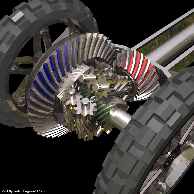
Conventional Differential - POV-Ray 3.6.1, 1/18/11

 Automobiles use differentials to allow the left and right drive wheels to rotate at different speeds. This prevents the wheels from skidding when making sharp turns. The drive shaft is directly connected to the pinion gear (shown in red). The pinion gear turns the ring gear (shown in blue), imparting a net rotation to the wheel axles. The differential pinion carriers or "spider" gears (shown in yellow) allow for different rotations between the left and right differential side gears (shown in green). The differential side gears are directly connected to the wheel axles. This design fails when one wheel loses traction (see Torsen Traction differential). Notice that the pinion and ring gears are spiral bevel gears.
 |
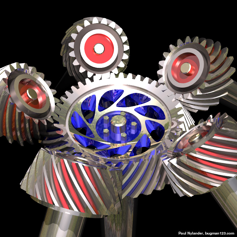
Torsen Traction Differential - POV-Ray 3.6.1, 1/21/11
 The Torsen Traction differential was patented by Vernon Gleasman in 1958. It takes advantage of worm gears to prevent the tires from slipping. If designed properly, the worm gears (shown in green) can turn the worm wheels (shown in yellow), but they cannot be turned by the worms wheels due to friction. In 1982, Gleasman joined Gleason Works, producer of 90% of the world's automotive bevel gears. There are three types of Torsen differentials (T-1, T-2, T-3). The one shown here is of type T-1.
Links The strange geometry of Gleason's Impossible Differential - interesting Popular Science article, dated February 1984 Lego Torsen Differential - by Rob Stehlik |
Spiral Bevel Gears - POV-Ray 3.6.1, 1/15/11
 Spiral bevel gears are generally quieter and vibrate less at high speed than regular bevel gears. Finding the exact shape of a spiral bevel gear tooth is not a trivial problem. Direct Digital Simulation (DDS) can be used to calculate the conjugate (or "footprint") of the tooth. This animation shows spur gears morphing into bevel gears, then into spiral bevel gears, then into helical gears, and finally back into spur gears again.
Links Spiral Bevel Company - has some free sample models, sells software for designing and analyzing spiral bevel gears Direct Digital Simulation for Gears - book on how to calculate and analyze conjugate profiles for spiral bevel gears |
Other Interesting Links
Masahiro Kikuno - watchmaker who makes some of the world's most amazing mechanical watches by hand
Curta Calculator - amazing mechanical calculator developed by Curt Herzstark while he was in a concentration camp, story narrated by Cliff Stoll
Gear Ring - the gears can actually rotate, by Kinekt Design
Gear Ring - 3D printed by Susan Hinton